
TYPE
(ME 4243 & ME 4202)
TEAM
Nathaniel S. Cannon
Charles Schaub
Shavonnah Moore
DATE
(10 months)
TOOLS
ABOUT
(Sponsored by Legacy Directional Drilling, LLC. for USD 10,000)
MY ROLE
AWARD
DESIGN CHALLENGE
Problem Description
Therefore, we design a prototype of an autonomous directional drilling machine that could completed in an economically feasible budget of $10,000 while having the potential to be replicated in a full-scale drilling system and safe for all personnel located near the rig while drilling.
Design Requirements
01. Imitate Full Scale Machinery
Our rig must be designed in a way that is scalable to a full-sized industrial drilling rig.
02. Protect Personel
Our rig must be safe for all personnel located near the rig while drilling due to any failures or unexpected events.
03. Operate Autonomously
Our rig must be able to function directionally drilling of the borehole without human interaction.
IDEATION & DEVELOPMENT
Concept Generation
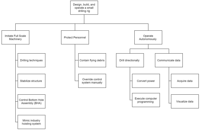
(Project Objective Tree)
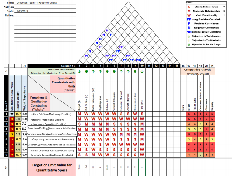
( The House of Quality (HOQ)

List of sub-systems of the prototype
01. Top Drive Assembly
02. Hoisting System
03. Bottom Hole Assembly
This assembly will apply a desired RPM to the inner shaft which directly relates to the amount of torque output from the drill bit.
This system will apply a desired weight on bit (WOB) and rate of penetration (ROP) to the bottom hole assembly (BHA).
The bottom hole assembly contains the downhole sensor, drill bit, and other components used to achieve directionality.
04. Structural Assembly
05. Circulation System
06. Instrumentation and Control
The structural assembly will maintain stability of the other sub functions of the drilling rig and provide safety for personnel operating the rig.
The circulation system will cool the bottom hole assembly during operation and remove any cuttings from the borehole during the drilling process.
The instrumentation will collect various data throughout the rig. This data includes temperature, position, true vertical depth, measured depth, weight on bit, RPM, and flowrate. The control system will take the output data from the instruments and make decisions based on the data.
Materials on the parts of prototype
Engineering Analysis
(Slideshow of engineering analysis on each of parts on the prototype)
MANUFACTURING & PROGRAMMING PROCESS
FINAL DESIGN
Product Architecture
The final project's prototype delivered was not able to be fully completed due to the COVID-19 shutdown.
Therefore some of parts on the prototype wasn't finish to be assembled into a complete structure of drilling rig. Those , specific electrical and mechanical components (only part of the non-drilling) test was validated before the shutdown. These tests included major components such as a ball screw for the hoisting system, all sensors and actuators, trajectory calculations, and control code where the results of the tests were compliant with the specifications.
Trajectory Control Algorithm
The control algorithms as shown above, at the top is the Input Parameters block. During this section of code, the program will take the coordinates from the operator that allows the program to start calculating trajectories. The algorithm moves to the next block labeled Calculate. Here, H1, R, and B1 are computed and sent to the top drive motor for orientation. H1 is the horizontal distance from the current point to the target point. R is the radius of curvature when sliding due to the fixed bent angle of the BHA. B1 is the azimuth angle from north to the horizontal line drawn between the current position of the bit to the target point.
After BHA is reoriented, vertical drilling starts and is carried out until the true vertical depth (TVD) sensor measures the kickoff point (KOP). Once the KOP is reached, the system will recalculate the azimuth between north and the horizontal line drawn between the current position and the target coordinate, this time using the tool face (TF) formula. If necessary, reorientation will take place, and the system will start building to the first target. While building, the bottom hole sensor will take readings of inclination (Am) and azimuth (Bm) and the TVD sensor will take measurements of measured depth (MDm).
Inclination target (At) will then be compared to inclination measured (Am) throughout the build, and when they are equal, the system will start drilling tangentially, or in a straight line. Once the system starts to drill tangentially, the system will monitor the TVD by reading the MD sensor and using the inclination reading from the bottom hole sensor to compute ΔV. ΔV will be added to the TVD at every reading of the sensors.
Once the calculated TVD (TVDc) is equal to the target TVD, the system will recalculate the TF required to build towards the second target. This angle will again be sent to the top drive motor, and the system will reorient. After the reorientation, system will build and drill tangentially again until the final target is reached.